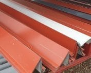
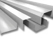
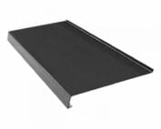
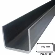
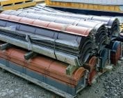
Sheet metal flashings
Planning the full chimney flashing detail on a sandwich panel roof
In brief
Chimney flashings must cover the junction where the penetration meets the roof covering and drain water away. On a roof made of sandwich panels, they require precise definition of the geometry and the coordination of several layers. The detail must not be limited to the coloured sheet metal visible on the outside. The termination of the panel and the correct seals must also be planned. The requirements for chimney safety and for the roof penetration remain a separate part of the design. A chimney, a duct enclosure and other equipment projecting above the roof may look similar from a distance. However, they require different solutions. Before selecting flashings, the type of penetration and the materials of its surfaces must be known. Information on the thickness and shape of the roof panel is also needed.
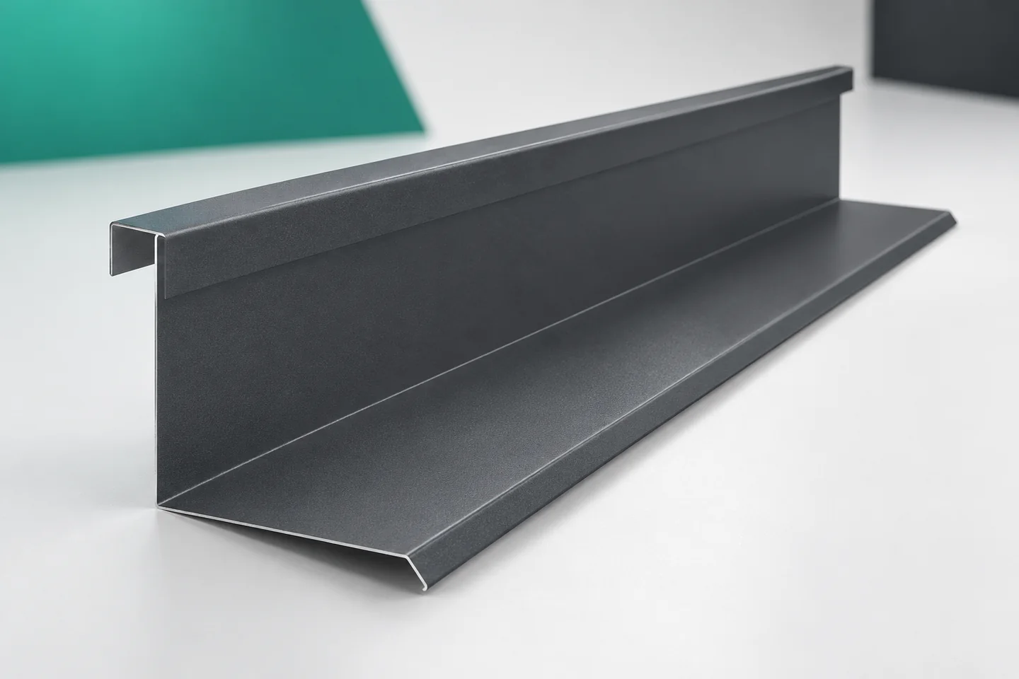
First establish the construction of the penetration
The contractor should have a detail that covers more than just the outline of the flashing. The position of the supports, the termination of the core and the intended seals are important. The opening in the panel must not be created solely on the basis of the chimney’s external dimension. Its design must correspond with the documentation for the entire penetration.
Distinguish between the front, side and rear
Water reaches the penetration from different directions. The part positioned higher up the slope receives the runoff from the roof, while the lower part discharges water onto the covering. The side chimney flashings connect these zones. For this reason, a single uniform strip does not always describe all four sides.
The roof slope and its profile must be taken into account. With a wide obstruction, the path of the water may require separate design. The dimensions of the rear element should not be derived from the front dimension alone. The drawing should also show the corner connections and the direction of the laps.
The panel termination requires its own cover
Once the opening is made, cut edges of the facings and exposed parts of the core are created. Their protection must be provided for in the system solution for the penetration. The external chimney flashing may conceal this location, but it does not automatically replace all the other layers.
It is worth planning the sequence of work so that access to the edges is not lost too early. Inspection before covering allows the accuracy of the cut and the condition of the material to be checked. Swarf and residues of protective coating should not be left in this location. Later removal of contamination can be difficult.
The seal is selected to suit both surfaces
The sealant used for the flashing must work together with the metal sheet and the material of the chimney or its casing. The application conditions and the product’s scope of use are important. The mere fact that it is a roof sealant does not determine compatibility with every substrate. A specific specification is required.
The sealant should not be used to fill an arbitrarily large gap resulting from incorrect dimensioning. First the flashing is adjusted and the joint is prepared. The geometry should direct water in a safe direction. The seal is part of this solution, not the only obstacle in the path of precipitation.

Allow for movement
The roof sheet and the element passing through the roof slope do not have to behave identically under the influence of temperature. The detail should allow for their interaction. Rigidly connecting all parts at random points can hinder the movement for which the flashing was designed.
This does not mean loosening the fastenings arbitrarily. Their arrangement results from the technical solution. During installation it must be checked that the laps, strips and seals remain consistent with this assumption. Chimney flashings require such control even when the roof is new and the surfaces appear even.
Material selection covers the coating and edges
Galvanised, aluzinc and colour-coated metal sheets are used for flashings, depending on the available range and the conditions of use. They should not be treated as identical materials. Compatibility with adjacent elements and the recommendations for the given covering must be checked.
The coating must not be damaged during adjustment. The sheet is cut with tools recommended for such work. At the corners, scratches and traces of repeated bending should be checked with particular care. Painting over a visible line alone does not allow assessment of whether the protection has been correctly restored.
Acceptance of the detail covers both sides of the roof
Finished chimney flashings must be inspected at the corners, the upper termination and the connection to the covering profile. From the inside, the extent specified in the penetration design is checked. Its completeness cannot be confirmed solely on the basis of a photograph of the outer collar.
Ridge caps, verge flashings, gutter aprons and starter profiles should form a consistent material set, but they will not replace the penetration elements. If non-standard sheet metal flashings are needed, they are prepared according to an approved drawing. The chimney’s fire protection solution requires a separate assessment appropriate to the given system.
Questions and answers
Does a sheet metal collar solve all the requirements of the penetration?
No. The flashing primarily concerns the junction with the roof covering. The structure, insulation and chimney requirements must be resolved in the full design.
Can the flashings be selected from the chimney width alone?
That is not enough. The dimensions of the other walls, the roof pitch, the panel profile, the position of the penetration and the method of connection to the casing are also required.
7 branches. Materials closer to your project.