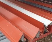
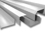
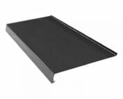
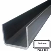
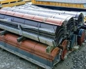
Flashings
Custom flashings for sandwich panels – bend geometry and fabrication tolerances
In brief
Unusual flashings allow areas not covered by the standard catalogue to be finished. However, they must be feasible to manufacture, deliver and install. The drawing should take into account not only the visible shape but also the actual substrate and the sequence of works. With sandwich panels, their locks, profiling and layer connections are additional factors. A good detail combines this information before production begins. First, establish what the flashing is to cover and where it is to direct water. A cover for a vertical joint is designed differently from a drip edge, and differently again from a capping. A similar letter outline does not determine the same function. The drawing should also show adjacent elements.
Start with the element’s function
Ridge caps, verge flashings and gutter aprons have clear places of application. A non-standard flashing requires an equally unambiguous description. It is worth giving it a name referring to a specific building junction. This avoids a situation in which the installer receives several similar profiles without information on their purpose.
Dimension the cross-section, not the perspective
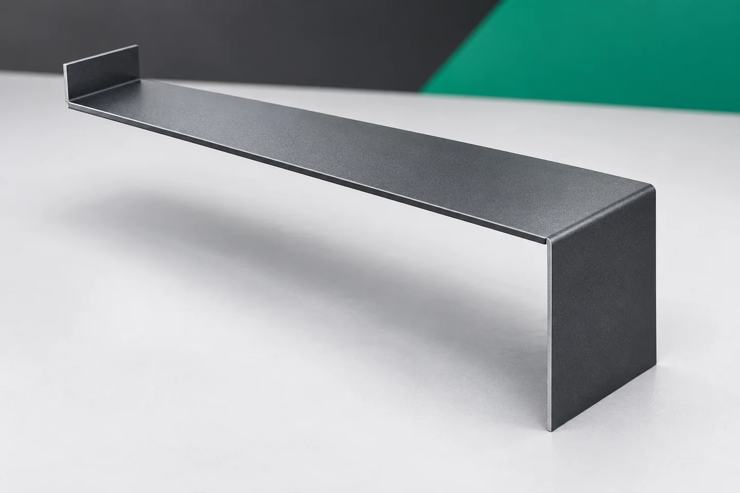
The basis of the order is a cross-section with leg dimensions and angles. A three-dimensional view can help identify the product, but does not replace this data. Edge folds and any changes in shape must also be marked. An omitted small section can change whether the element can be fitted.
The length of the finished flashing is given separately. It must not be confused with the developed width, i.e. the width of material needed to form the cross-section. It is worth using one unit of dimensions on the order sheet. This means the person preparing production does not have to guess the meaning of the numbers.
Establish how dimensions are to be read
External, internal and centreline dimensions are not the same. With a simple, loosely fitted element the difference may seem small. In a tight joint with the panel it becomes significant. The dimensioning method must therefore be agreed with the flashing installer.
Perfectly sharp corners should not be assumed. Bending has a real radius, depending on the material and technology. The internal clear width of the profile may therefore differ from a simplified sketch. If the flashing is to cover an edge or fit between elements, an assessment of such fit is needed.
Leave room for installation
Even a correct finished joint dimension does not always allow the flashing to be slid into place. The direction in which it is fitted and access to the fasteners are what matter. The sequence of works and any component parts must be anticipated. A one-piece profile may be awkward where installation takes place after the wall has been closed.
Starter profiles are fitted at a different stage from end trims. Similarly, chimney flashings require coordination with the works at the roof penetration. Unusual flashings should therefore be checked against a simple installation sequence model. This saves cutting a finished component later.

Select the material before approving the bends
Galvanised, aluzinc and coated steel sheets differ in their surface specification. Forming possibilities also depend on the thickness and grade of the substrate. A very tight shape cannot be approved and then the material changed freely afterwards. Both decisions should be made together.
The colour side must be specified. For an asymmetric flashing, turning the sheet over may produce the wrong component. The expected surface finish should also be defined. If the part is to match an existing cladding, a sample is often more helpful than a general colour description alone.
Take into account the condition of the completed structure
The design drawing should be compared with a measurement of the installation location. Changes in the position of supports and the thickness of layers may affect the actual cross-section of the flashing. Each construction error should not be compensated for by randomly widening the trim. The cause of the difference must first be established.
The dimensions and permissible deviations should allow the components to be assembled without excessive stress. This does not mean adding arbitrary clearance in every direction. The required fit results from the function of the joint. Long sections and locations where the wall runs at a varying line require particular attention.
Check the first piece before the whole batch
For a complex flashing, it is worth agreeing a check of a trial section or the first piece. The angles, the visible side and the feasibility of installation can then be assessed. If a correction is necessary, it should be entered on the drawing. A verbal comment alone at delivery does not organise the next batch.
Finished components should be marked in accordance with the schedule. Surfaces and transport deformation are also checked at acceptance. Unusual flashings do not gain value from their complicated shape alone. Their advantage is the precise solution of a specific location while maintaining feasibility of production and inspection.
Questions and answers
Is a render sufficient to order flashings?
No. A dimensioned section, length, material and identification of the visible side are required. A render can only supplement this information.
Can every flashing be made in any thickness?
This should not be assumed. The limitations depend on the shape, the sheet metal and the bending technology. Feasibility must be confirmed before production.
7 branches. Materials closer to your project.