PIR insulation
EFYOS BLUE SMART A and waterproofing: how to plan a coordinated layout
At a glance
In the SMART A system, the waterproofing follows the surface of the slopes. If a single element is oriented incorrectly, even the correct covering technology on its own will not restore the drainage path. Acceptance of the geometry must therefore take place before the insulation is covered. The plan should also show the junctions between fields and the points where the direction of water flow changes. The EFYOS BLUE SMART A scope must be described together with the layers adjoining its surface. An important junction detail is the lowest section of insulation next to the outlet. The basis for coordination is the falls plan with the individual tapered boards marked. Before selecting materials, the outlet level and the end heights of each fall field must be established so that the sequence of layers has a real reference.
Function of the board in the cross-section
A correct layout should allow the drainage to be combined with a suitable insulation thickness at the outlet. The functions of the other layers must be defined separately.
The right product and the scope of its data
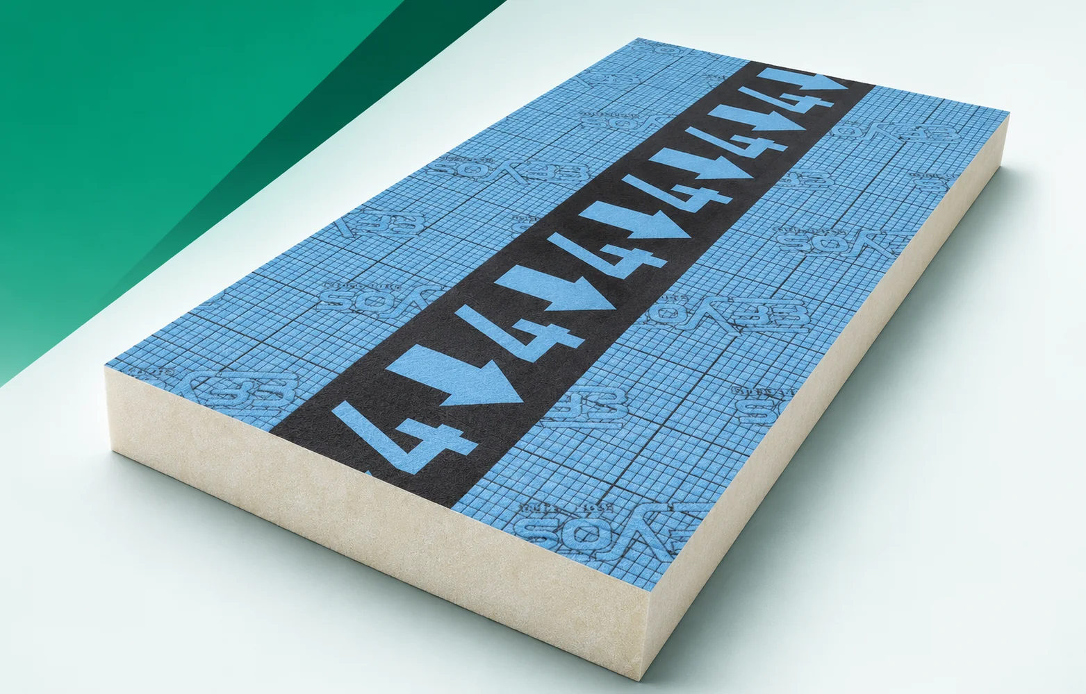
In EFYOS BLUE SMART A, the PIR core is faced with aluminium on both sides. The manufacturer states a format of 1200 × 1200 mm, straight edges and a nominal slope of 2.08%; lambda 0.022 W/(m·K), compression CS(10)150, reaction to fire class E. A complete order also includes the elements that form the roof surface, so square metres alone are not enough. We consider SOPREMA PIR boards within the scope of a flat roof with tapered insulation and point drainage. The properties of the finished board result from the core and facings together, and installation consists of laying the factory-made boards in the planned layer sequence.
Scope of the example comparison
Example: a 2.40 m section at a constant slope of 2.08% gives a height difference between the ends of approximately 49.9 mm. The slope value is based on the documentation for the EFYOS BLUE SMART A family, but the example does not define the entire field or the starting elevation. The level at the outlet depends on the substrate and the underlying layers, and the detail of the lowest section of insulation next to the outlet must be developed separately. This is not the thermal resistance of the roof. Base the inspection of the work on the falls plan with the taper markings and the actual course of the sections.
The calculation involving EFYOS BLUE SMART A describes the stated quantity, not automatically the class of the entire system. The key assumption is the nominal slope of 2.08%. The result must be compared with the limitation defined as the range of height difference between the outlet and the perimeter. With regard to this section, the direction in which the thickness increases must be checked before the field is covered. A falls plan with the markings of the individual tapers is helpful, as it shows the position of each layer. Only then can a covering that reproduces the designed slopes be considered without implicitly transferring rules from another combination of materials.
How to assess the proposed change
The variant based on the decision to relocate the water collection point must be considered through to the end of the cross-section. In the second step, the following must be considered: the behaviour of the outlet and the change in the thickness distribution. With EFYOS BLUE SMART A, both proposals must retain the requirements at the location described as the lowest section of insulation next to the outlet. Reversing a similar wedge or omitting the base layer must be ruled out, because such a simplification changes the basis of comparison. The final scope should be confirmed by the designer of the drainage and tapered insulation. For the selected solution, a schedule of specific slope elements and their positions is needed, consistent with the materials located directly below and above the insulation.
Surface and joint finish
The surface of EFYOS BLUE SMART A consists of a blue aluminium facing on the slope element. Its type must be taken into account when selecting the layer with which it will work. In the documentation, the simple joint of the boards in the designed wedge arrangement must also be identified, instead of replacing the actual geometry with a general symbol. Acceptance should be based on the schedule of element numbers consistent with the layout plan. For this reason, the covering reproducing the designed slopes should only be installed after an agreed inspection. On the drawing, it is worth highlighting the lowest section of insulation next to the outlet, because that is where the course of the connection changes.
The sequence of works follows from the layout
Before laying EFYOS BLUE SMART A, support must also be ensured for the thinnest sections at the outlet. The schedule should include an inspection of the element described as the lowest section of insulation next to the outlet. For acceptance, a falls plan with markings for the individual wedges must be prepared, indicating any execution-related changes. After this inspection, work can proceed to the scope that is the covering reproducing the designed slopes. The sequence should be coordinated by the designer of the drainage and tapered insulation, especially when different layers are installed by different crews. This makes it possible to separate the tasks of the polyurethane insulation from the works ensuring the other functions of the cross-section.
A specification ready for pricing
An enquiry for EFYOS BLUE SMART A should clearly indicate a flat roof with tapered insulation and point drainage. The description should be accompanied by a schedule of specific slope elements and their positions, so that the supplier knows the adopted variant. A separate item may be the work needed to connect the drainage with the appropriate insulation thickness at the outlet. It is worth requesting a specification of the changes caused by any replacement of the facing or geometry. Each such proposal should again take into account the range of the level difference between the outlet and the perimeter. After selecting the solution, the schedule of element numbers consistent with the layout plan must be retained as the basis for identifying the material on site. In such an order, the polyurethane boards are part of a specific system, not a category of freely interchangeable sheets.
7 branches. Materials closer to your project.