PIR insulation
α-therm WALL: joining IDELCO boards in a cavity wall
At a glance
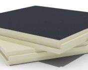
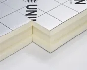
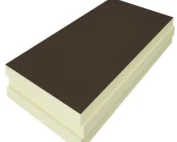
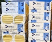
IDELCO α-therm WALL is a PIR board with aluminium laminate on both faces, intended for insulating cavity walls. In the cross-section it restricts heat flow, while the masonry, the wall ties and the outer leaf perform their own functions. Selection therefore covers both the insulation thickness and its connection to the reveal, lintel, sill and base. The required cavity geometry must be maintained and drainage of water must be provided for. The laminate and the tongue-and-groove joint do not replace flashings or structural elements. Below we discuss how these parts of the wall work together, how to set out the boards and how to check the edges before they are covered. The broader term “polyurethane boards” is not sufficient to identify the WALL variant.
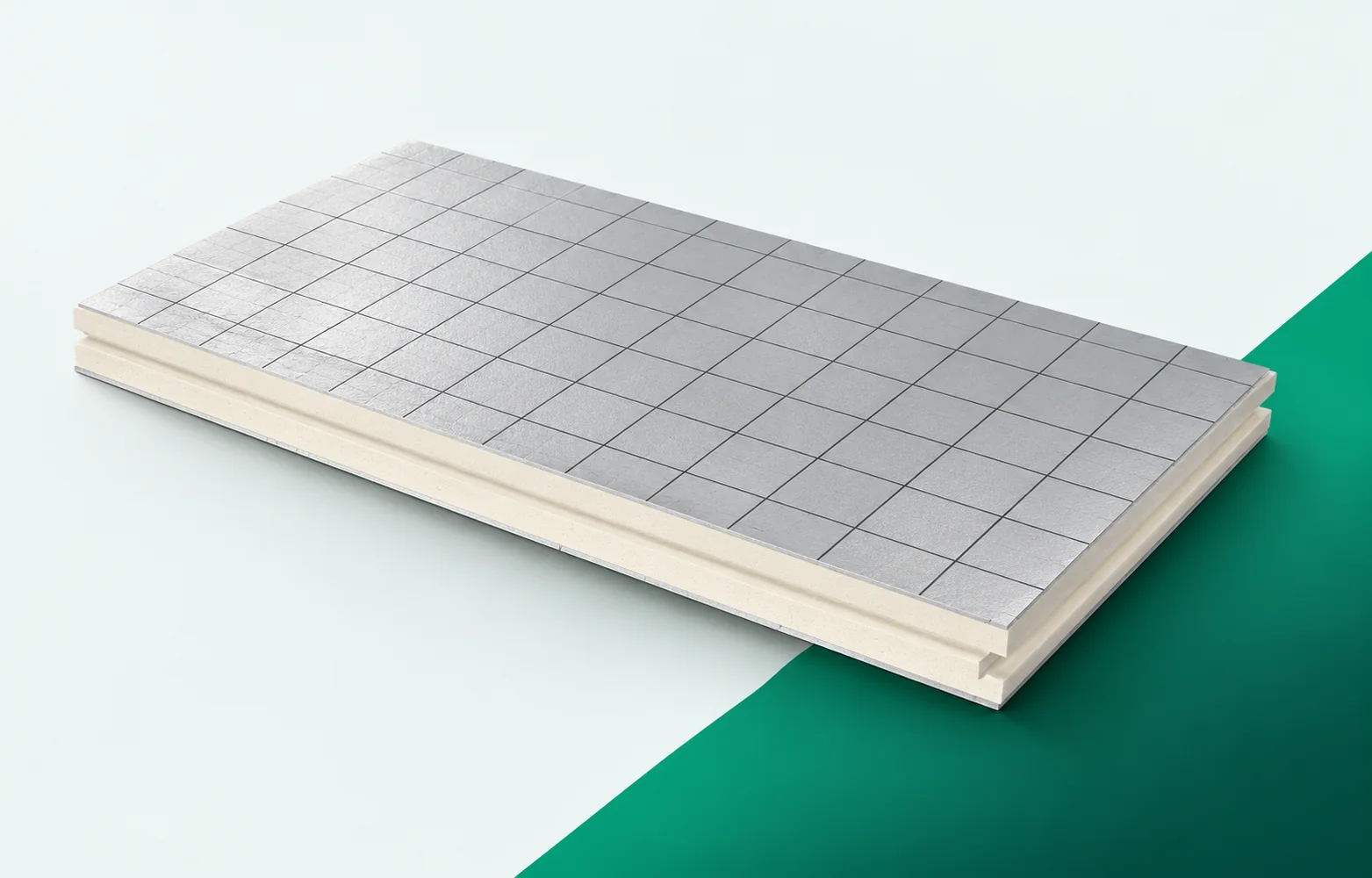
α-therm WALL PIR boards between the layers of a wall
At the opening, show the load-bearing wall, the WALL layer and the external cladding separately. The small thickness of the thermal insulation makes it easier to match the cross-section, but it does not transfer structural tasks to the laminated insulation. The position of each part must correspond to the detail of the actual reveal.
Lambda and the geometry of the building component
The thermal conductivity of α-therm WALL is 0.022 W/(m·K). The data sheet lists several thicknesses, so thermal conductivity alone does not settle the choice. When comparing two assemblies, consider the 100 mm α-therm WALL board with R_D 4.50 m²K/W.
The thermal resistance of the WALL board does not describe the influence of the anchors or the geometry of the corner and lintel. For the required thermal result, select both the insulation thickness and its terminations. The wall comparison should cover the field cross-section and those places where the direction or continuity of the thermal insulation changes.
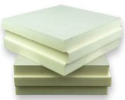
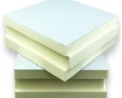
Polyurethane insulation with tongue and groove
Join the tongue and groove without damaging the profile and without open joints. When cutting the edge element, you change the factory finish, so resolve the detail at the last row and at the reveal deliberately and show it on the installation drawing.
For the WALL 1200 × 600 mm format, determine the laying direction and the cuts at the perimeter. A cut edge loses the factory profile; it must be fitted without breaking the tongue and without leaving a gap. On the plan, mark the final rows and the places requiring edge inspection.
Water at the reveal and under the sill
The wall cladding must drain water also at openings and at the lower part of the building element. WALL insulation has a different task, which is why the drainage path cannot be derived solely from the laying of the boards.
Under the window sill, coordinate the termination of WALL with the flashing, the water drainage and the possibility of the wall drying out. The aluminium laminate does not replace the waterproofing of the masonry. The sequence of works should make it possible to install the protection against water and to maintain the continuity of the thermal insulation before access is closed off by the covering layer.
The correct data for the wall variant
For WALL, the data sheet states CS of at least 120 kPa at 10% deformation and reaction to fire F. The compression result does not define the permissible permanent load. A similar facing on the ROOF product does not entitle one to transfer its parameters to the wall product.
In the wall documents, check the full WALL designation and the scope of the intended application. These are what link the assessment of mechanical properties to the specific product. The brand and appearance of the laminate are not proof of equivalence with another board.
Insulation with polyurethane: quantity and inspection before covering
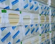
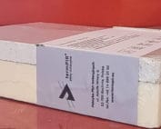
Calculate the WALL quantity from the net wall area, the format and the cutting layout at openings. The allowance depends on the building geometry. Also include in the scope of works the inspection of the edges before the insulation is closed with the facing.
When comparing WALL offers, include the protection of the material and the acceptance of the insulation at the time when the joints are still visible. A damaged profile can make a connection difficult that can no longer be inspected later. Therefore agree the bill of quantities, the method of cutting and the timing of the inspection before covering.
A case worth considering
In the cavity wall, α-therm WALL limits heat flow. The load-bearing capacity of the masonry, the anchoring of the facing and the water drainage path are separate tasks. After fitting the insulation, check that the required cavity geometry is maintained. The tongue and groove alone does not close the entire detail. The selection of layers must lead to a compliant wall section.
7 branches. Materials closer to your project.