Installation and construction
How to set out modular tile-effect sheets on a pitched roof
In brief
Begin planning the layout of modular metal roof tiles by measuring the actual roof slopes, not by counting panels straight away. Check whether the dimensions from the design match the completed structure, because even a small difference changes the width of the last cut. Mark the eaves, ridge, hips, valleys and the actual position of openings. Describe each slope separately and indicate the drawing’s viewing side to avoid swapping left and right slopes. Use the effective cover width for the specific model to determine rows and columns, since overall dimensions include overlaps. Also check the position of ribs relative to battens and the possible installation directions allowed by the profile’s construction.
How to prepare a drawing of the roof slope?
Start by measuring the length, width and diagonals. Mark the eaves line, ridge, corners and roof valleys. Window openings and service penetrations should have their actual position, not just an approximate symbol. It is worth describing each roof slope separately. This prevents the number of panels from being assigned to the wrong part of the roof.
If the dimensions come from the design, they must be compared with the completed structure. Even a small difference can change the width of the last cut. A curved slope should not be corrected by randomly shifting the overlaps. First the geometry of the support and the way the edge is finished must be assessed. Only then can the module grid be laid out reliably. On the drawing, also mark the side from which you are viewing the slope. This small detail prevents the right and left slope from being swapped when the cutting plan is passed between people.
Which panel dimensions should be entered into the plan?
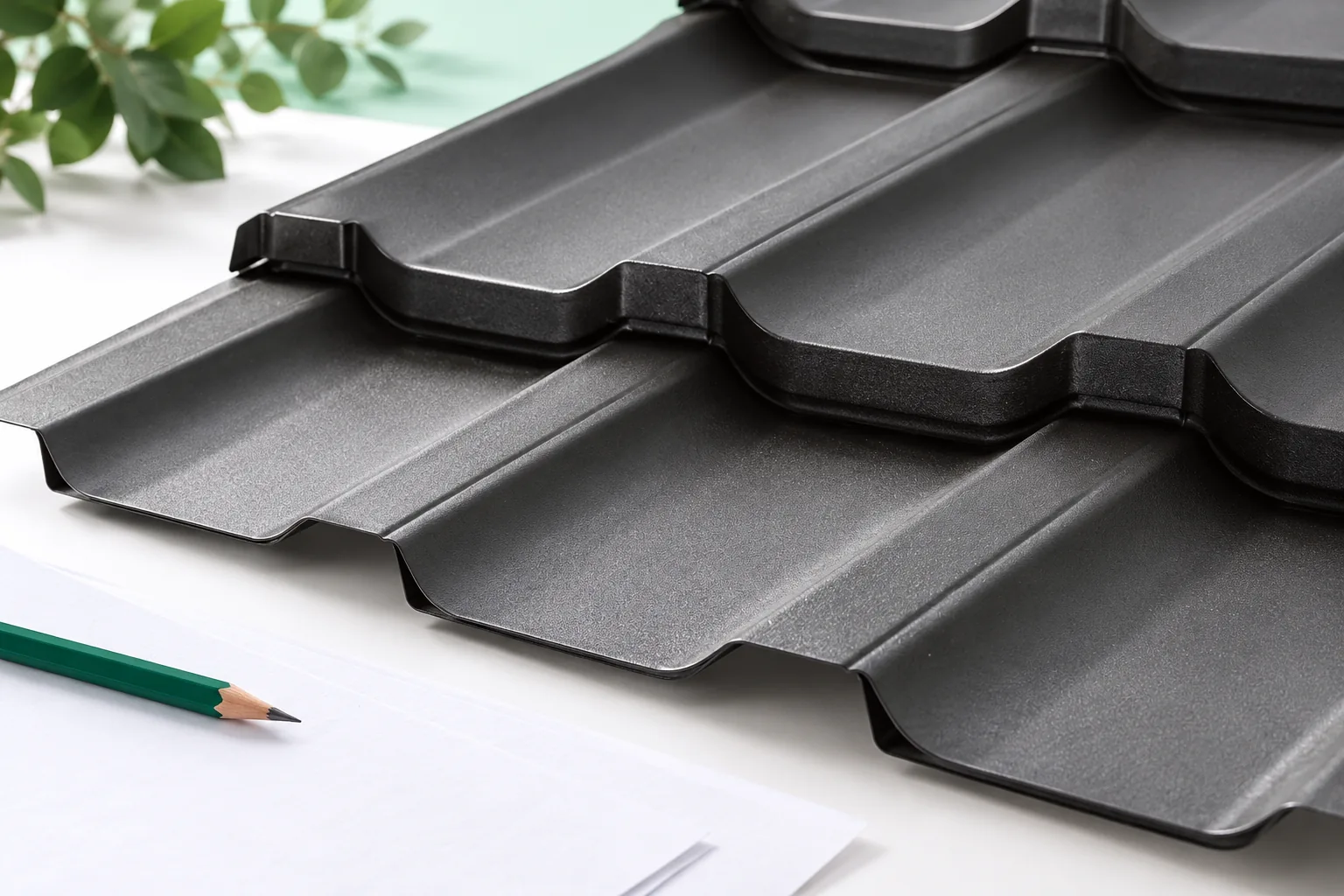
Planning the number of rows and columns requires the length and width of the effective coverage. Overall dimensions include the overlap sections and cannot replace them. If you use too large a width, a shortage of material will appear after a few panels. The drawing should refer to the exact model, not to a general description of tile-effect metal roofing.
Also check the position of the ribs relative to the battens. The module length determines the repetitive support rhythm, but the dimension at the eaves may be different. In the plan it is worth marking the first and last row. They should not be determined independently of the details. The projection into the gutter and the finish under the ridge must fall within the requirements of the specific system.
From which side should laying begin?
The possible installation directions result from the construction of the profile and the edges. Some panels allow the covering to be laid in several variants, others require a specific overlapping sequence. The visible symmetry of the wave does not justify arbitrary freedom. Drainage grooves and the points where several sheets join are particularly important.
The choice of direction should also take into account access on the roof and limiting walking on the finished surface. The placement of packs and the way panels are handed up are worth agreeing with the crew. If the instructions permit an alternative sequence, the more convenient one for the specific slope can be chosen. However, the joining rules should not be changed just because it is easier to reach the neighbouring element.

How should panels be arranged at the roof valley and corner?
On triangular or trapezoidal slopes it is worth checking several starting points. Shifting the grid can change the widths of the edge cuts and the use of material. This does not have to mean changing the permitted overlap arrangement. The plan should preserve the direction of water flow and the correct fixing of each section.
A cut-off piece can only be used where its geometry and method of connection fit. It is not enough for it to cover a similar area. Turning a panel over may change the side of the overlap or the direction of the profile. It is worth marking the fragments intended for reuse on the drawing. The declared saving then has a concrete basis, rather than following from the assumption that nothing will be wasted.
What should be done at windows and penetrations?
Openings divide the panel layout and require the correct flashings. The plan should ideally show which elements will be cut and how they will be supported. A very small fragment is not always convenient to fix. It is worth considering a permitted shift of the layout if it allows narrow strips at the window flange to be avoided.
The flashing should not be matched solely to the point where the sheet ends. This connection must work together with the layers beneath the covering. Water from the higher part of the roof slope should be safely drained away. Before you order the panels, also check the compatibility of the accessories with the height and shape of the profile. A similar colour does not ensure a correct fit.
How do you turn the plan into an order schedule?
Count the full panels, the cut elements and a justified allowance. The schedule should indicate what results from the calculations and what remains a reserve. Count the flashings and fasteners separately. It is worth keeping the numbering of rows or groups if the roof is complex. This will make it easier to compare the delivery with the plan and reduce mistakes during the works.
Before final approval, the plan should be checked by a contractor familiar with the chosen system. They may notice difficult access or a detail requiring a different sequence. It is also worth establishing how changes on site will be documented. If the layout is modified, the new solution must still preserve the principles of support, overlaps and water drainage. The plan is a working tool, not merely a way of calculating the number of pieces.
7 branches. Materials closer to your project.