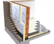
PIR insulation
Pitched roof with Powerroof: membrane, joints and load transfer
At a glance
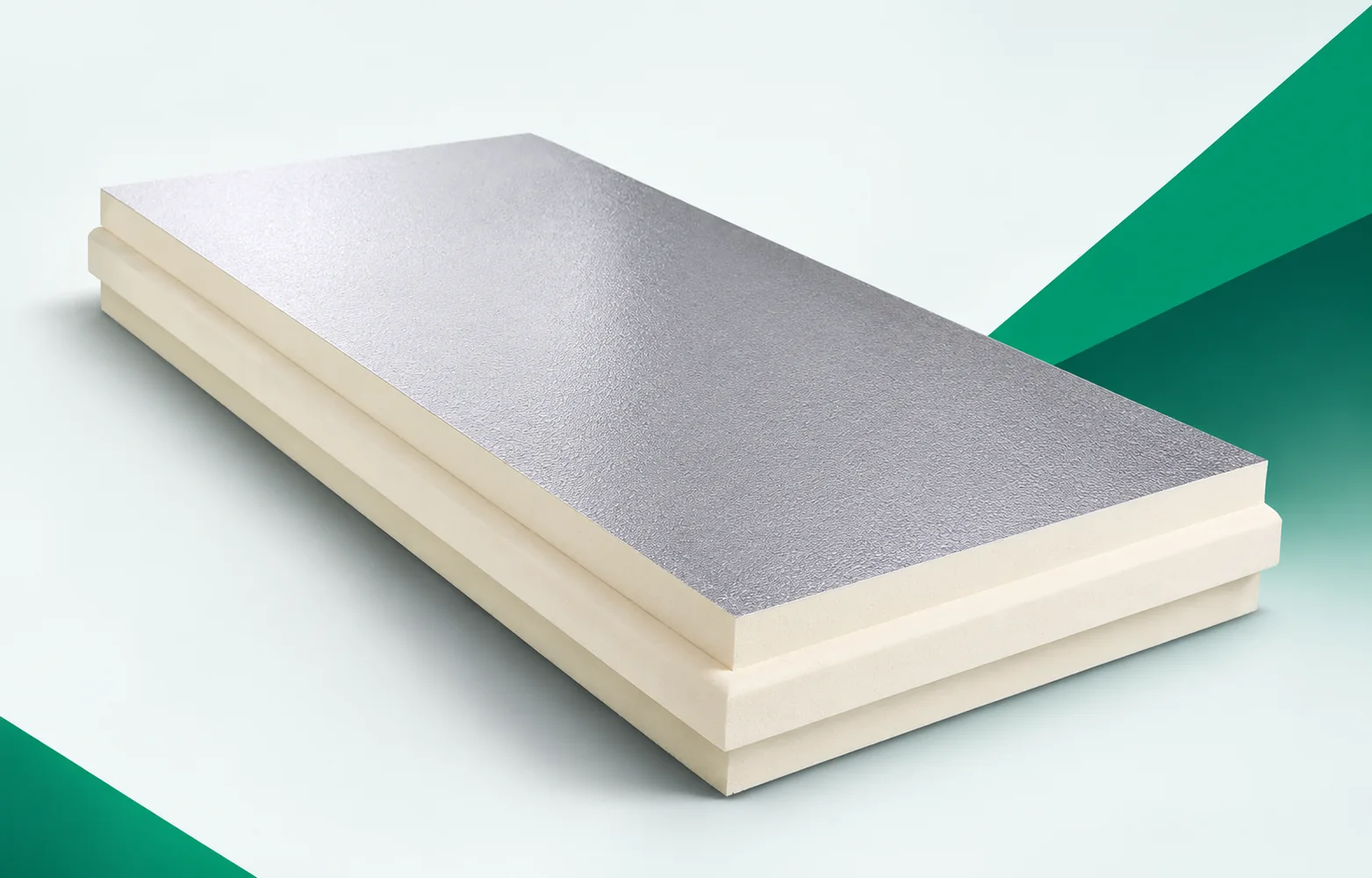
In a sloping roof, Powerroof works together with the structure, the protective layer and the components beneath the covering. It cannot be assessed independently of the fixings. The roof slope must simultaneously drain water, transfer loads and maintain the continuity of the insulation at the edges. Recticel Powerroof is a PIR board for above-rafter thermal insulation of sloping roofs. It has an aluminium facing and a tongue-and-groove joint on all four edges. When selecting PIR boards for the system, draw the above-rafter Powerroof layer running over the timber structure of the sloping roof in the actual cross-section. Powerroof must be run over the rafters while maintaining correct fixing of the entire covering, because the remaining layers must fit the same solution. The individual layers must work together, because continuous insulation does not replace the components that transfer forces from the covering to the structure.
The role of the cladding and the other layers
The adopted assembly should allow the over-rafter system to be used without omitting the support and changes in roof geometry. To the description of the solution, add the course of the insulation layer, the height of the roof slope and the design of the connection to the timber elements so that the completeness of the layers can be verified.
Support and method of connection
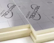
The gross format of Powerroof is 2400 × 1200 mm, while the coverage is 2380 × 1180 mm; this difference is created by the tongue and groove on the edges. Therefore, the number of boards is determined from the net area, not from the gross dimension.
Continuous polyurethane insulation requires a correct detail; in the description, include the difference between the 2400 × 1200 mm format and the 2380 × 1180 mm coverage. The number of Powerroof boards must be determined from the net coverage before adding cutting losses, before the layout is considered ready for execution. The instructions for the full field do not cover all terminations, because ordering by the gross dimension underestimates the area that can actually be covered. The installation drawing should make it possible to determine the number of full boards before adding losses at roof valleys and roof windows. Before you accept a substitute, check the coverage area, the number of rows and the layout of cut pieces around obstacles on the roof slope in relation to the adjacent layers.
The Powerroof tongue and groove organise the connection of the boards, but the above-rafter layout requires more than correctly joining the edges. At the eaves, the layer must connect with the wall insulation. At the window, a different geometry and water protection are added. The fastening still transfers forces to the structure. These locations must be shown in separate details, because a drawing of the uniform field does not explain how they are executed.
Air, vapour and water tightness
A layer protecting the roof from water must run above Powerroof, with correctly laid laps and terminations. The aluminium facing of the board does not by itself seal any penetration through the roof slope.
When selecting the protective layers, discuss where the chimney passes through the thermal insulation and the separate water-draining layer. At the chimney, the rain-protection layer must be closed regardless of how the PIR boards are cut, because watertightness must also be achieved at the joints between the different parts of the system. In the finished building envelope, the polyurethane foam needs a covering, because the aluminium facing of Powerroof does not itself form the chimney flashing and its terminations. The adopted detail must allow the continuity of the water-protection layer to be planned regardless of how the PIR boards are joined. In the description of the installation sequence, indicate the run of the laps, the treatment of the penetration and the protection of the open roof slope during a break in installation; this information should be consistent with the documentation for the complete system.
Thermal effect of the entire building envelope
For Powerroof, a lambda of 0.022 W/(m·K) is declared. With the assumed thermal resistance of the building envelope, this allows the thickness of the insulation layer to be reduced.
In the calculation of the system, include the resistance determined from the thickness of Powerroof and the lambda of 0.022 W/(m·K). In the calculation of the roof slope with Powerroof, also include the fasteners that penetrate the thermal insulation layer, so as not to combine parameters from different material variants. A change of material name alone does not give equivalence, since a favourable value for the middle of the board does not automatically describe the result at every roof detail. When comparing polyurethane boards in alternative arrangements, the space saving must be related to the result for the full cross-section rather than to the foam alone. In both variants, compare the fixing parameters, the course of the joint at the eaves and the actual insulation thickness at the terminations for the same function of the building envelope.
What the assessment of the entire solution covers
For Powerroof, CS(10/Y)150 and reaction-to-fire class D-s2,d0 are given. These values alone do not make PIR non-combustible, nor do they give the roof fire resistance – that must be demonstrated for the entire system.
The specification of requirements for the system should explain the D-s2,d0 class and CS(10/Y)150 indicated for the Powerroof board. The Powerroof Euroclass must be distinguished from the fire resistance and load-bearing capacity of the complete roof, and the scope of assessment must correspond to the actual configuration of the assembly. The significance of the parameters changes with the scope of assessment, because neither the Euroclass nor the compression result on its own determines the load-bearing capacity of the covering fixing. Before approving the structure, the mechanical and fire requirements must be checked at the correct level of assessment of the solution. In the application documents, look for the documentation of the entire roof and the manner in which loads and wind forces are transferred to the structure, and compare them with the designed layers.
Complete specification for pricing
When pricing Powerroof, calculate by net covering area, with the geometry of the roof slope and the treatment of openings. Also add the effects of the new thickness of the system at the eaves and windows.
When pricing the “polyurethane insulation” item, analyse the scope of rebuilding the eaves and flashings after adding the Powerroof above-rafter layer. The cost of the above-rafter layer should take into account changes to the flashings resulting from the new height of the roof slope, so that the scope of purchase corresponds to the complete specification of the solution. An omitted item may come back as additional work, because preserving the existing attic construction may require a larger scope of work on the outside. A well-described scope allows renovation variants to be compared, taking into account the interior space and changes in the geometry of the roof slope. At the acceptance of the delivery and the works, confirm the net covering area, the bill of quantities for the fixing, flashings and works at the existing roof windows, so that they match the agreed system.
7 branches. Materials closer to your project.