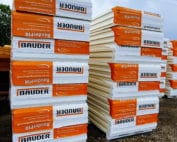
PIR insulation
BauderPIR FA beneath roof equipment supports
At a glance
At the base of the equipment, the requirements for load-bearing capacity, thermal insulation and tightness meet. FA can form part of this cross-section, but each element must have a defined load-transfer path. Sealing the screw is not a structural design of the support. Likewise, a favourable contact pressure does not confirm that the waterproofing upstand is correct. The cross-section under consideration is a roof with equipment supported on the layers above the insulation. The role of BauderPIR FA must be described together with the layers adjoining its surface. An important connection point is the contact area of the roof equipment foot. The basis for coordination is the support drawing showing the load-transfer path and protection of the covering. Before selecting materials, the force transferred by the support and its actual contact area must be determined, so that the layer sequence has a real reference.
Function of the board in section
A correct configuration should combine thermal insulation performance with permissible deformation under load. The role of the other layers must be defined separately.
The correct product and the scope of its data
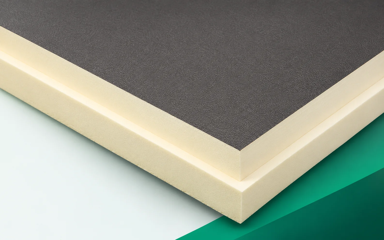
For BauderPIR FA, the data sheet states λD 0.022 W/(m·K), CS(10/Y)120 and reaction-to-fire class E, while the Polish data sheet of September 2026 separately states 24 kPa under long-term load at 2% deformation — this is not the same as the test result at 10%. The PIR core and the facings form a factory-made board; its place in a roof with equipment supported on layers above the insulation is determined by the support design covering all layers, because CS is not the load-bearing capacity of the finished roof.
Scope of the example comparison
Example: a force of 1.20 kN and an actual contact area of 0.030 m² give an average pressure of 40.0 kPa (force divided by area). With BauderPIR FA it is not enough to relate this to the 120 from CS — the data sheet also states 24 kPa under long-term load at 2% deformation, so the distribution of the force through the entire detail must be traced. This is neither a design nor an approval of the support; the forces must reach the structure in accordance with the design, and the nominal outline of the footplate does not guarantee contact over the entire area.
The protective layer under the footplate does not serve solely to separate materials. Its contribution to transferring the force must be confirmed in the adopted configuration. A nominally wide base may have a different actual contact with the substrate. The entire outline area should therefore not be assumed without verification. It is precisely at this boundary that the pressure calculation and the protection of the sealed covering meet.
The calculation involving BauderPIR FA describes the stated quantity, not automatically the class of the entire system. An important assumption is the separate assessment of short-term compression and permanent load. The result must be compared with the limitation defined as the actual size of the load-transferring surface area. With reference to this cross-section, the verification of force, bearing area and deformation over time must be kept separate. A support drawing showing the load transfer path and the protection of the covering, from which the position of each layer can be seen, is helpful. Only then can the covering together with the protective layer beneath the support be considered without automatically transferring principles from another combination of materials.
How to assess the proposed change
The variant based on the decision to increase the actual load-distribution area must be considered through to the end of the cross-section. In the second step, the action must be considered: a separate support solution transferring the load in accordance with the design. With BauderPIR FA, both proposals must maintain the requirements at the location described as the contact area of the roof-mounted equipment foot. The figure of 120 kPa must not be regarded as a ready-made permissible support load, because such a simplification changes the basis of comparison. The final scope should be confirmed by the designer of the support and roof loads. For the selected solution, a set of documents concerning supports, penetrations and the service walkway is required, consistent with the materials located directly below and above the insulation.
Surface and joint finish
The surface of BauderPIR FA is the aluminium facing of the board beneath the protective layers. Its type must be taken into account when selecting the layer with which it will work. In the documentation, the joint of the insulation in the vicinity of the equipment base must also be identified, instead of replacing the actual geometry with a general symbol. Acceptance should be based on the document containing the pressure calculation and the conditions of its long-term action. For this reason, the covering together with the protective layer beneath the support should only be installed after an agreed inspection. In the drawing, it is worth highlighting the contact area of the roof-mounted equipment foot, because that is where the course of the joint changes.
The sequence of works follows from the layout
Before BauderPIR FA is laid, the transfer of forces from the equipment to the structure must be ensured in accordance with the design. The schedule should include inspection of the element described as the contact area of the roof-mounted equipment foot. For acceptance, a support drawing showing the load transfer path and the protection of the covering must be prepared, indicating any execution-related changes. After this inspection, work can proceed to the scope comprising the covering together with the protective layer beneath the support. The sequence should be agreed under the lead of the designer of the support and roof loads, especially when different layers are installed by different teams. This makes it possible to separate the tasks of the polyurethane insulation from the works ensuring the other functions of the cross-section.
Specification ready for pricing
An enquiry for BauderPIR FA should clearly indicate a roof with equipment supported on layers above the insulation. The description should be accompanied by a set of documents concerning supports, penetrations and the service route, so that the supplier knows which variant has been adopted. A separate item may be the work required to combine thermal performance with the permissible deformation under load. It is worth asking for a breakdown of the changes caused by any substitution of facing or geometry. Every such proposal should again take into account the actual dimension of the load-transferring surface. Once the solution has been selected, the document with the pressure calculation and the conditions for its long-term performance must be retained as the basis for identifying the material on site. In such an order, polyurethane boards are part of a specific system, not a category of freely interchangeable sheets.
7 branches. Materials closer to your project.