PIR insulation
Bonded roof with Recticel Powerdeck F. What should be checked before selecting the system?
At a glance
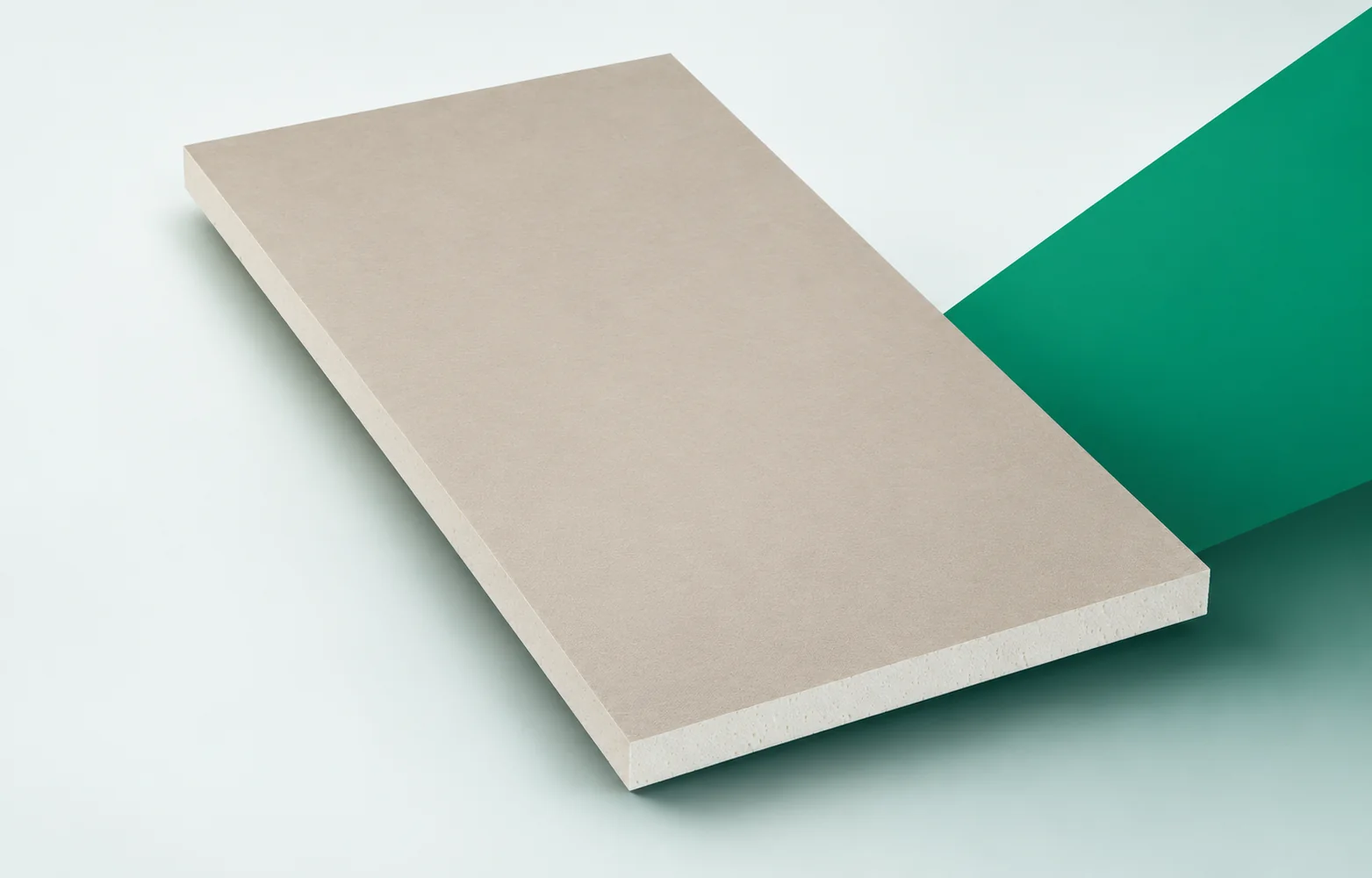
In a bonded roof, durability is determined by the chain of connections between the layers. Powerdeck F is intended for use with suitable waterproofing solutions. Every transition between the substrate, adhesive, board and covering requires confirmation of compatibility. Recticel Powerdeck F has a PIR core faced on both sides with a mineralised glass fleece. The product is intended for flat roofs with a suitably selected covering. When selecting PIR boards for the system, show the mineralised glass fleece of Powerdeck F as the surface that bonds to the covering in the actual cross-section. The facing of Powerdeck F must be matched to the materials in contact in the adopted roof system, because the remaining layers must fit the same solution.
The role of the facing and the other layers
The individual layers must work together, because a similar colour of the PIR core does not determine whether the surface is compatible with the selected membrane. The adopted set should allow the choice of product to be based on the requirements of the specific roof build-up. Add the type of facing, the adopted covering and the documentation of their mutual compatibility to the description of the solution, so that the complete set of layers can be verified.
Support and method of connection
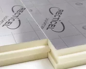
In the order, first settle the geometry of the board edge: Powerdeck F is available with straight edges or in a milled rebated variant. This choice determines how adjacent boards are brought together and how cuts are made at the ends of the field, so confirm the format and thickness for the variant you are actually ordering.
Continuous polyurethane insulation requires correct detailing; in the specification, include the straight-edge or rebated variant indicated for the Powerdeck F version being ordered. The side geometry of Powerdeck F must be agreed before the cutting plan and the number of boards to be ordered are determined, before the layout is considered ready for execution. The instructions for the full field do not cover all terminations, because a change of format or side profile affects cuts and the actual surface coverage. The installation drawing should allow the delivery geometry to be agreed before the number of boards and the direction of successive rows are determined. Before you accept a substitute, check the format on the order, the way the elements are brought together and the support at the end of the field in relation to the adjacent layers.
For Powerdeck F, the bonding specification should identify the specific material set and the conditions for its use. Merely stating the chemical type of adhesive is too general. It is necessary to know how the mineralised fleece and the layer on the other side of the joint are prepared. The system requirements also include installation details. Without these determinations, it is easy to confuse the compatibility of two trade names with confirmed suitability of the entire solution.
Compatibility of the protective layers
The selection of the bonded or self-adhesive membrane together with the fastening system must be specified for Powerdeck F as one set. The fact that the adhesive is called polyurethane or bituminous does not settle the suitability of the bond with the board’s mineralised fleece.
When selecting the protective layers, discuss the connection with the bonded or self-adhesive membrane within a clearly defined set of materials. When bonding, the compatibility of the membrane and the bonding material with the mineralised fleece must be confirmed, because tightness must also be achieved at the joints between the different parts of the system. In the finished assembly, the polyurethane foam needs a covering, because the general chemical name of the adhesive does not replace confirmation of the compatibility of the specific product. The adopted detail must allow the joining method to be selected together with the surface preparation and the installation conditions. In the description of the installation sequence, state the system instructions, the requirements for the substrate and the method of checking the connection before the details are covered; this information should be consistent with the documentation for the entire set.
Thermal effect of the entire assembly
Calculate the thermal resistance of the Powerdeck F layer using the declared lambda of 0.026 W/(m·K), inserting the specific board thickness. When comparing variants, do not adopt the lambda of another product, because the result will not relate to this material.
In the system calculation, include the calculation of the Powerdeck F layer with the declared lambda of 0.026 W/(m·K). The thickness of Powerdeck F must be calculated with its own lambda of 0.026 W/(m·K), so as not to combine parameters originating from different material variants. A mere change of material name does not produce equivalence, since stating a lambda of 0.022 from another product would lead to an incorrect result for this board. When comparing polyurethane boards in alternative arrangements, the thickness must be determined from the Powerdeck F parameters rather than from the general name PIR. In both variants, compare the design resistance, the available layer height and the calculation of the full roof section for the same function of the building element.
What the assessment of the whole solution covers
For Powerdeck F, the CS(10/Y)120 declaration concerns the behaviour of the board under load, not the entire roof. The reaction-to-fire class E is given for thicknesses from 40 mm; B-s2,d0 relates to the specific end use. Therefore, when checking the mechanical behaviour and the behaviour during fire, these data must be linked to the actual substrate, fixing and complete set of layers, because a change of covering or fixing method may go beyond the scope of the previously assessed arrangement.
The summary of requirements for the system should explain the CS120 declaration and the conditions of the class E given for Powerdeck F from 40 mm. The end-use classification must be linked to the actual substrate and fixing of Powerdeck F, and the scope of the assessment must correspond to the actual configuration of the building element. The significance of the parameters changes with the scope of the assessment, because a change of covering or fixing may go beyond the scope of the previously assessed system. Before approving the structure, the requirements of the whole roof must be retained when considering the mechanics and behaviour in fire. In the application documents, look for the board thickness, the complete set of layers and the documentation corresponding to the actual method of fixing them, and compare them with the designed layers.
Purchase in line with the adopted system
The purchase of Powerdeck F covers not only the board thickness but also the method of making the joints. The quotation for the item “polyurethane insulation” must therefore include substrate preparation, the required layers and details, so that the price of the board does not obscure the work needed for a tight covering. On acceptance of the delivery and the works, compare the bill of quantities for the boards, connecting materials, substrate works and flashings with the agreed system.
When pricing the item “polyurethane insulation”, analyse the cost of substrate preparation and of connecting the insulation with the selected waterproofing system. The quotation should include substrate preparation and all materials needed to make the covering, so that the scope of purchase corresponds to the complete specification of the solution. An omitted item may come back as additional work, because a favourable price for the board does not automatically include priming, bonding and making the flashings. A well-described scope allows the expenses leading to a finished, tight covering with specified requirements to be compiled.
7 branches. Materials closer to your project.