Installation and construction
How should supports be selected for a panel wall exposed to wind?
Key points in brief
Supports should not be positioned solely for the convenience of column layout. A wall panel carries wind pressure and suction, and its deflection affects both appearance and the performance of connections. The correct spacing results from the loads and the data for the specific product. The number of spans, the width of supports and the parameters of both steel facings are also important. A single panel may rest on two or more supports. The distance between adjacent supports is the span. In the tables, single-span and multi-span arrangements have separate conditions. A more favourable result cannot be selected without conformity with the actual frame.
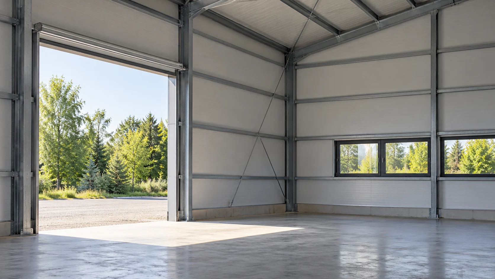
Panel length is not the same as span
On the drawing, mark all supports, member ends and opening locations. Also establish their widths. The panel may be sufficiently strong in the field, while the connection or bearing zone still requires modification. The calculations and details should cover these parts together.
Dimensions must match the completed frame.
Wind matters for a small building too
The action depends on location, height, geometry and surroundings. Openings affecting internal pressure are also relevant. A low load should not be assumed merely because the workshop is single-storey. Particularly demanding suction conditions may occur at corners and edges.
The data are determined by the designer for the specific building. Do not transfer them from an adjacent hall without verification. After extension or installation of a large door, the assumptions may change. It is therefore worth considering the support layout together with the final building form and the way the openings are used.
Read the table from the header and footnotes
Check the panel type, core, thickness and facing parameters. Then establish the span diagram and the load direction. Tables may give permissible loads for a given span or maximum spans for a load. The units and the method of comparison with the calculations must be consistent.
Note whether the values refer to characteristic or design loads. These quantities must not be mixed. Also check the ultimate limit state and the serviceability limit state. The deflection criterion may be decisive even though the member has not yet reached its strength limit. This affects the behaviour of the connections and the appearance of the surface.
When comparing two products, do not choose solely on the basis of the table that allows the greater spacing. Check whether it uses the same deflection criteria and fixing conditions. In a wall with large glazed areas, deformations may affect adjacent details. The design should ensure that all parts work together. The table is a tool for checking this, not a promise of a single maximum spacing independent of the surroundings.

Colour and temperature are part of the service conditions
The external cladding heats up differently from the internal one. The temperature difference can cause deformation of the panel. The tables use specific assumptions, often separated by colour groups. A dark façade should not be assessed according to the conditions assumed for another group without confirmation.
In a workshop with intermittent heating, it is also worth passing on how the building is used. This does not change the table on its own, but it helps the designer assess the adequacy of the assumptions. A planned change of colour or of a long element to another variant should be checked before ordering.
Openings and fixings may require local modification
A window, gate or larger duct interrupts the wall layout. The remaining panel sections and the framing need adequate support. It is not enough that the full panel of this thickness appears in the table. The cut-out may change its behaviour and may require an additional rail.
Equally important is the number and load-bearing capacity of the fasteners at the support. Correct span alone does not ensure proper fixing. In edge zones, a different arrangement may be needed than in the middle of the wall. The solution should be shown on a drawing so that the installer does not have to guess the details from a general screw count.
Compare the approved layout with the completed structure
Before installation, measure the actual distances and support widths. Check their plane, thickness and the condition of the connections. If the completed frame deviates from the design, the change must be assessed. A small increase in span should not automatically be regarded as insignificant.
Keep the table and the version of the data used for the selection. For later alterations, it will then be clear which assumptions applied. Do not remove a rail solely to make room for a cabinet or appliance. The support is part of the verified system, and changing it requires a reassessment of the behaviour of the entire wall.
Short answers
Does a thicker panel always allow greater spacing?
Not automatically. The specific configuration, the structural scheme, the loads and the deflection conditions must be compared. The fixings and the width of the supports may also determine the outcome.
Can the value be read between the columns of the table?
Only by the method permitted in the given documentation. The range should not be extended beyond the stated values on one’s own initiative, nor should interpolation rules be transferred from another system.
7 branches. Materials closer to your project.